- Posts: 36
- Thank you received: 2
×
Questions regarding all aspects of Fiber Optics manufacturing and production go here.
Fiber Optic Patch Cable PC, APC or UPC
- Mrs Bella Tse
- Topic Author
- Offline
- Junior Boarder
-

Less
More
5 years 3 months ago #3061
by Mrs Bella Tse
Fiber Optic Patch Cable PC, APC or UPC was created by Mrs Bella Tse
To make better contact between the ends of the two fibers, the ferrule end faces of the
fiber optic patch cable
is usually polishing into different structures. Standard polishing methods are PC, APC, and UPC. PC/APC/UPC represents the front end structure of the ceramic ferrule.
Different fiber end face finishes
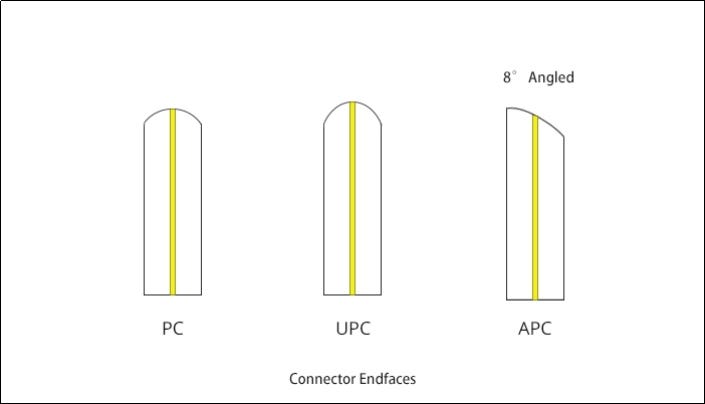
PC (Physical Contact).The two end faces are polished to be slightly curved or microspherical, and the fiber core is at the highest point of the bending. This eliminates the air gap and forces the fibers into physical contact.
UPC (Ultra Physical Contact) is based on the PC to optimize the end face polishing and surface finish, the end face looks more dome-shaped. The end face of the UPC connector is not entirely flat, and there is a slight arc to achieve more accurate connecting.
APC (Angled Physical Contact). The end face of APC is usually polishing into an 8-degree angle. The 8° angled bevel makes the fiber end face tighter and reflects light through its beveled angle to the cladding instead of returning directly to the source, providing better connection performance.
Different physical appearance
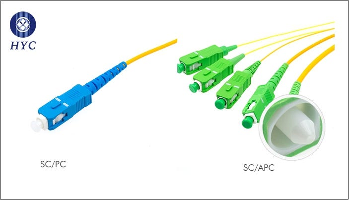
The APC fiber optic connector is usually green. UPC/PC connectors are easily identified by their blue color on the connector boot.
Insertion loss and return loss
Different polishing styles determines the quality of optical fiber, which results in different performances regarding the connector's insertion loss and return loss. Insertion loss refers to the signal loss caused by the connector or cable. In general, the typical insertion loss of PC, UPC, and APC connectors should be less than 0.3dB. Compared with APC connectors, UPC connectors are usually easier to achieve low insertion loss due to the smaller air gap. Insertion loss can also be caused by a tiny particle of dust trapped between the connector end-faces. A single dry debris particle could even damage the fibers and ferrules.
Return loss, also known as reflection loss, is a parameter representing the signal reflection performance. Usually expressed in negative dB value, the higher the value of the setting, the better. The end faces of APC connectors are beveled, so the return loss of APC connectors is usually better than UPC connectors. In general, the return loss of the PC fiber cable is -40dB. UPC return loss is higher relative to PC, generally at -55dB (or even higher). APC industry-standard return loss is -65dB. With the UPC connector, any reflected light is directly reflected back to the light source. The beveled end face of the APC connector allows the reflected light at an angle into the cladding instead of reflecting it directly to the light sources. This is the main factor that causes the return loss to differ.
Applications
PC is the most common grinding method for optical fiber connectors, which is widely used in telecommunication operator equipment. UPC is commonly used in Ethernet network equipment (such as ODF fiber distribution frames, media converters and fiber switches, etc.), digital, cable television and telephone systems. APC is generally used in optical radio frequency applications such as CATV, and also in passive optical applications, such as PON network structures or passive optical local area networks.
Connector connections need to be in the same end face structure; for example, APC and UPC cannot be mated together , because doing so will resulting in poor connector performance. However, the end faces of PC and UPC fibers are flat, and the difference is in the quality of grinding. Therefore, the mixed connection of PC and UPC will not cause permanent physical damage to the connector.
Please Log in to join the conversation.
Moderators: Erik A Macs, Peter J Stewart-Hay
Time to create page: 0.061 seconds


 How to resolve AdBlock issue?
